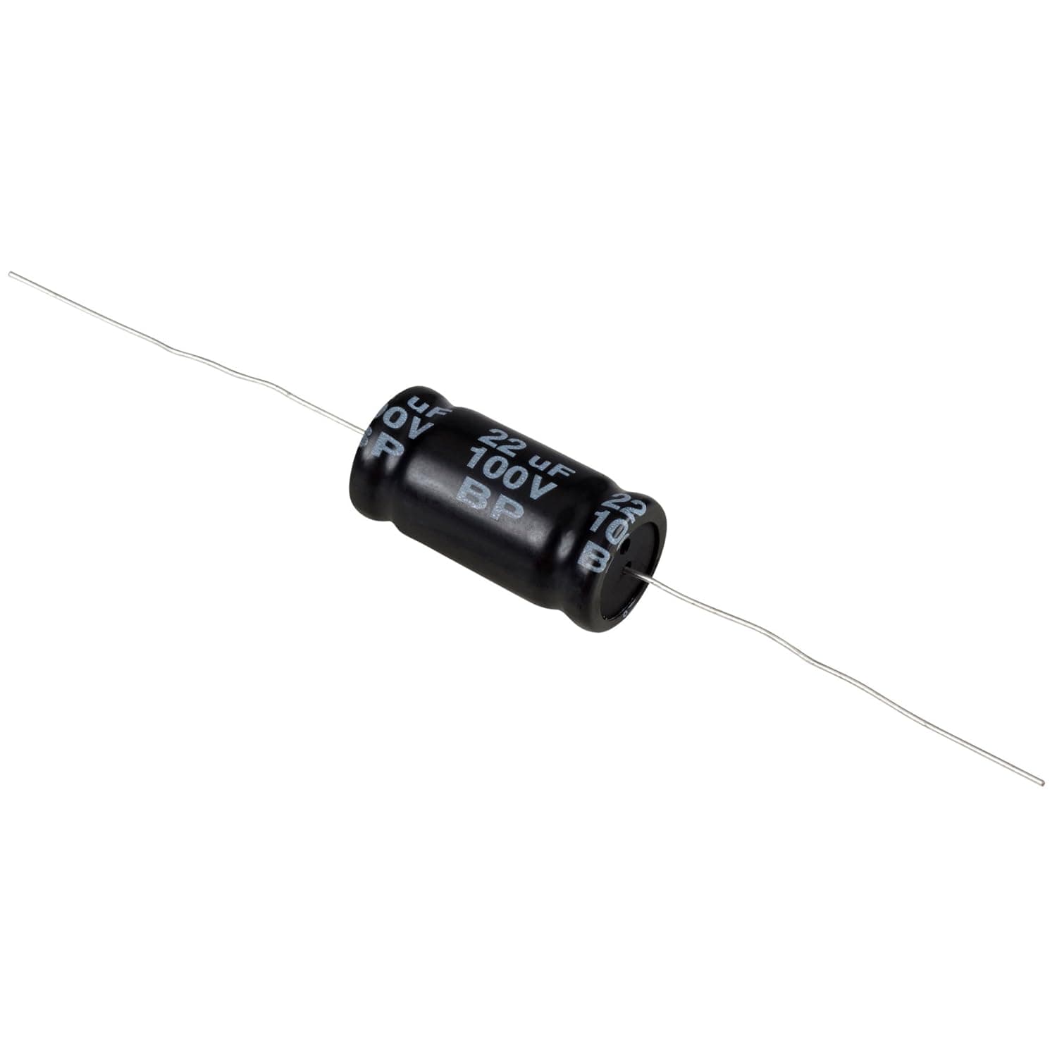
The 電解非偏光キャップ | 22 µF | 10% is a non-polarized (bipolar) electrolytic capacitor rated 22 µF, ±10% tolerance, 100 V. It looks like an unremarkable passive part, but put it in the wrong place and the result is a thin-sounding channel or a circuit that does nothing useful.
This article works through where the value makes sense, and where it will disappoint, with the numbers you can actually check.
Overview
The short answer: this part earns its place in passive speaker crossovers and as a drop-in for aging bipolar electrolytics in vintage audio gear. Because it has no polarity, the classic "installed it backwards" failure simply cannot happen, so if you can solder, the only real risk left is physical fit.
Choose it to "improve a line output" or "upgrade a headphone jack" and the capacitance is in the wrong ballpark, as the table below shows.
The listing rating was 4.4 out of 5 stars (88% favorable) as of the 2026-07-16 capture, but that average comes from only 8 reviews, so it carries almost no statistical weight.
The spec sheet lists no brand or manufacturer either, which is normal for generic passives. That leaves exactly one useful decision input: whether the numbers fit your circuit.
Capacitance: Where 22 µF Fits and Where It Doesn't
In series with a load, a capacitor forms a first-order (6 dB/oct) high-pass whose -3 dB corner is f = 1/(2πRC). For 22 µF:
| Load impedance | Approx. -3 dB corner | Verdict |
|---|---|---|
| 8 Ω (tweeter) | ~900 Hz | Practical crossover value |
| 4 Ω (tweeter) | ~1.8 kHz | Higher, but usable |
| 32 Ω (headphone out) | ~230 Hz | Bass loss. Too small |
| 10 kΩ (line input) | ~0.7 Hz | Far below audio. Oversized |
| 47 kΩ (line input) | ~0.15 Hz | Grossly oversized |
The key takeaway is that 22 µF is a speaker-level value (single-digit ohms), not a line-level or headphone-level one. Into a line input the corner sits well under 1 Hz, so any audible difference comes from the part's character, not from the value.
Into 32 Ω headphones it starts rolling off around 230 Hz, which is an audible loss of low end; that position needs a much larger capacitance.
A ±10% tolerance is good for an electrolytic — generic bipolar parts are often specified at ±20%. Even so, ±10% spreads the 8 Ω corner across roughly 820–1,000 Hz.
Build a stereo pair and that spread becomes a left/right mismatch you can hear as a shifting image. Measure and match two close units if you have a capacitance meter, or just buy a few extras if you don't.
Compatibility Guide
The supplied compatibility note is a single line: soldering is required, and the part does not plug into any standard PC connector. In practice that means the host board must have been designed for leaded parts in the first place.
Mounting is through-hole, so it goes onto a PCB, a perfboard, or point-to-point wiring inside a speaker or amplifier. Modern motherboard and sound-card audio stages are usually built from surface-mount parts, and there is simply nowhere to put a leaded capacitor on those.
Check the mechanical dimensions before ordering. Non-polar electrolytics are commonly built from two polarized sections back to back, so they tend to be fatter and taller than a polarized 22 µF / 100 V part.
The earlier version of this article quoted a lead pitch around 5 mm, but at this capacitance diameter, pitch, and height vary by product, so measure your hole spacing and your enclosure clearance rather than assuming. Inside a cabinet, also check clearance to heatsinks and damping material, and make sure vibration will not fatigue the leads.
Read the 100 V rating carefully. A 100 V swing into 8 Ω corresponds to several hundred watts, so for home use there is ample voltage headroom.
But electrolytics specify DC withstand voltage and AC capability separately, and for continuous AC signal duty the ripple-current and AC-voltage limits bind first. Neither a temperature rating (85 °C / 105 °C) nor a ripple-current figure is included in the data for this part, so if you intend to use it in a high-power speaker network or a power supply, confirm both on the product page or datasheet.
If they are not published, pick a different part for that job.
One safety limit matters more than the rest: "no polarity" does not mean "mains rated." Do not use this capacitor across AC line voltage or as a motor-run capacitor.
Those applications require safety-approved X/Y-class or motor-run parts.
Product Info
rmation
The specifications are 22 µF capacitance, 10% tolerance, 100 V rating, non-polarized electrolytic type, through-hole mounting. No brand or manufacturer is listed, so treat it as a generic part.
Warranty is limited to the seller's initial-defect policy; there is no manufacturer support to fall back on. Positioning is entry-to-mid DIY: far cheaper than an equivalent film capacitor, at the cost of ESR, high-frequency behaviour, and long-term stability.
On price, the only data attached to this article is an eBay keyword search (captured 2026-08-16, currency USD, price shown as "see listing") with no fixed figure. An earlier version quoted roughly ¥2,888, which is high for a single generic 22 µF electrolytic and may reflect a multi-pack or an unrelated item.
This article therefore states no price. Before buying, confirm both the current price and whether the listing is one piece or a bulk pack — for parts at this level, quantity and shipping dominate the real cost.
One more quirk worth knowing: the price query is the Japanese product name sent to an international marketplace. Searches like that surface unrelated listings, so the cheapest result is not necessarily this part.
To gauge a real market price, search the English specification instead — "22uF 100V non-polar (bipolar) electrolytic".
Film Capacitors Compared
A 22 µF film capacitor (MKP/MKT) offers lower ESR, better long-term stability, and cleaner crossover behaviour. The price is volume and money: 22 µF in film is many times larger and can cost an order of magnitude more, and in a tight enclosure it may not physically fit at all.
The electrolytic's advantage is that it is cheap, compact, and polarity-free. For prototyping — sweeping a crossover point, or getting old equipment working again — it takes fewer steps.
Paralleling a 0.1–1 µF film part to lower high-frequency ESR is a common trick, but the audible benefit is often too small to confirm without measurement, so do not over-invest in the expectation.
Build with the electrolytic, then substitute film when you are optimizing the final result.
Recommended Users
- DIY speaker builders — in series with an 8 Ω tweeter the corner lands near 900 Hz (about 1.8 kHz at 4 Ω), making first-order experiments cheap to iterate.
- Vintage repair — if the original was a bipolar electrolytic of the same 22 µF at 100 V or less, this drops straight in with no orientation to worry about.
- Breadboard and prototype work — swapping values repeatedly is low-risk when polarity cannot be wrong.
- Anyone practising soldering — a forgiving leaded part where mistakes are cheap.
It is a poor fit if you do not own a soldering iron, if your board is surface-mount only, if you are chasing last-percent tweeter clarity, or if you want a power-supply smoothing capacitor (non-polar parts are not built for that, and no ripple rating is given).
Installation and Verification
- Photograph the original part's value, rating, orientation, and position before removal.
That photo is your rollback plan. 2.
Measure the delivered part. Any meter with a capacitance range will do: check it sits inside ±10%, and for stereo use note the channel-to-channel difference.
Measure hole spacing and vertical clearance before bending leads.
Solder quickly.
Electrolytics dislike heat, so leave a little lead length and heatsink with tweezers if needed. 5.
Check for shorts to adjacent pads visually and with a meter before powering up. 6.
Start at low volume. Orientation is free in a speaker circuit, but wiring mistakes show up here.
Before You Buy
Start by distrusting the listing data. For this article the price reference is a Japanese-keyword search on an overseas marketplace, the source product page has no confirmed price attached, and the category is recorded generically as "other".
Auto-collected listing metadata — manufacturer, part number, quantity — does not always match the physical item, so verify the product from the images and title yourself. Whether the listing is a single piece or a pack is the single most common misunderstanding at this price point.
Second, do not misjudge the order of magnitude. As shown above, 22 µF is a speaker-level value; in a line-level coupling position the corner sits below 1 Hz and the value itself changes nothing audible.
"Bigger capacitance means more bass" does not apply here, and on a low-impedance headphone load the same part is actually too small and thins the low end.
Third, electrolytics age on the shelf. Long-stored stock can arrive with capacitance already drifted, and electrolytic life depends strongly on temperature — the usual rule of thumb is that life roughly doubles for every 10 °C cooler.
No temperature rating, ripple rating, or load-life hours are provided for this part, so if it will sit near a heat source or run continuously, measure the delivered unit and look for a published datasheet first.
Finally, respect the hard limits. Never use it on AC mains or in motor circuits.
And if the goal is modifying PC audio, confirm the board was designed for leaded parts before ordering — on a surface-mount-only board this capacitor is not an option, and any modification voids your warranty.
FAQ
Q. Is orientation really irrelevant? A.
Yes. It is non-polarized, so there is no correct direction.
Note the asymmetry, though: a non-polar part can replace a polarized one, but a single polarized part cannot replace a non-polar one.
Q. What crossover frequency does 22 µF give? A.
As a first-order high-pass, roughly 900 Hz into 8 Ω and 1.8 kHz into 4 Ω.
The ±10% tolerance spreads the 8 Ω figure over about 820–1,000 Hz.
Q. Wouldn't a film capacitor be better? A.
Electrically, yes. But 22 µF in film is far larger and more expensive, and may not fit.
Build with the electrolytic, then upgrade selectively.
Q. Can I use it in motherboard or sound-card audio? A.
Only if the board takes leaded parts; surface-mount-only boards cannot host it. Also check the original value — 22 µF is usually oversized for a line-output coupling position.
Q. How many should I buy for stereo? A.
Two minimum, but buy a few extra so you can measure and match. Confirm whether the listing sells singles or packs.
Q. Can it smooth a power supply rail? A.
Not recommended. Non-polar electrolytics are not built for that duty, and no ripple-current rating is published for this part.